top of page
Assembling PC
WHAT IS IT ?
-
Here we are going to remove all the parts of a computer.
-
And assemble the parts together.
-
A basic computer has some basic parts we are going to open such as:
-
CPU
-
Monitor
-
Speaker
-
Keyboard
-
Mouse
-
So here we need some tools like Screw Driver to remove all the parts of CPU.

Screw Driver
Screws
CPU (Control Processing Unit)
-
CPU is the most important part a computer system.
-
We are going to open the CPU apart and discuss every part of it.
-
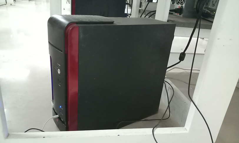
This below picture is a running CPU.


-
After opening the metal cover from the left side of the CPU, we can see all the small component connected to the motherboard.
-
Take all the components out of the cabinet.
-
Remove all the connection from the motherboard.
-
It looks like as below picture.
-
We will discuss the small components here.
Hard Disk Drive
DVD Drive
Motherboard
SMPS
Under the cabinet
Cabinet
CPU
I/O Shield

Top View of Motherboard
No Processor
CPU Socket
South Chipset
-
Remove all the connection from the motherboard.
-
It looks like as below picture.
-
We will discuss the small components here.
-
Connect the 20 or 24 pin ATX connector and the 4-pin power supply control connector to the motherboard.

Back Panel Connector Port
ATX 12v Power Connector
(4 pin)
ATX Power Connector
(20 pin)
RAM Slots
(Dual Channel)
4 SATA Ports
(Data)
CMOS Battery
PCI Connector
-
Ther are 2 types of connectors you will find.
-
SATA connectors are the data cables, which will connect to Hard Drive, optical drive and external drive.
-
One end plugs into a port on the motherboard.
-
Power Cable, we will get from SMPS.
-
This cable connects to the extenal devices and to motherboard.

SATA Connectors
Power Connector
-
SMPS provides all the power supply to the the board.
-
There are different types of connectors and different colors of wire are present.
-
Different color of wires carry different voltages.
-
It provides 3.3v, 5v, 12v and more.

Input Power Supply (230v)
For Motherboard
(20 pin)
For External Drive (12v)
For Motherboard
(5v)
-
Here is the back pannel connector port.
-
PS/2 port is for mouse and Keyboard.
-
3 paralel ports are form printer, display and projector.
-
One LAN port is there for ethernet connection with 4 USB port.
-
For audio section 2 input and 1 output port are present.
-
Green audio port: computer speakers or headphones.
-
Pink audio port: microphone.
-
Blue audio port: MP3 player, CD player, DVD player, turntable, electric guitar etc .

PS/2 port
(for mouse & keyboard)
LAN port
USB Port
VGA
For Projector
For Printer
Audio port
-
Disconnect the Hard disk from the power supply and the motherboard.
-
Here all the data including OS are being stored.

Upper view
Bottom View
SATA port
Power port
-
Mount the DVD-ROM drive.
-
It is used to reading or writing data to or from optical discs.
-
After connecting the ATA cable to the device, hook it up to the power supply.

Backside View
Power port
ATA port

Front View
-
Here is a extenal DVD drive, which can be connectd through USB.
-
It can be used as reading and writing from a optical disc.

-
Put out RAM form the moterboard.
-
RAM is a volatile memory and requires power to keep the data accessible.
-
If the computer is turned off, all data contained in RAM is lost.
-
Here we have 2 RAMs with front and back view.

Front view
Back view
RAM
-
A heat sink with cooling fan is mounted above a processor.
-
Cooling fans are necessary to aid in cooling the system.
-
Without them, the CPU would overheat and cease functioning.

Heat Sink
Cooling Fan
Power Cable
-
The central processing unit (CPU), also called a processor, is located inside the computer case on the motherboard.
-
It is sometimes called the brain of the computer, and its job is to carry out commands.
-
Here the processor is taken out from the socket.

CPU Socket
CPU
(Processor)
-
Assemble all the parts back to the original to make it work.
-
Connect the power supply from SMPS:
-
4 pin for motherboard
-
20 pin for motherboard
-
4 pin for Hard Disk Drive
-
4 pin for Optical drive.
-
Connect the SATA cable from motherboard to Hard Disk Drive and Optical Drive for data flow.
-
And connect the power supply and IO devices to CPU.
bottom of page